
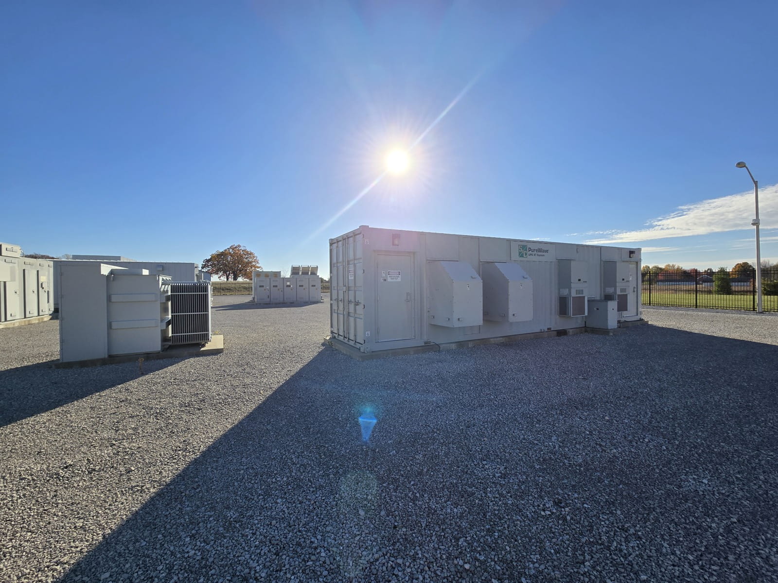
BatteryEnergyStorageSystems
Storage that supports the network instead of leaning on it: grid-forming control, three-per-unit overload for ten seconds, and insulation monitoring that keeps working while the system runs.
- Standard range
- 365 kWh – 50 MWh+
- MV connection
- 33 – 35 kV direct
- Response
- < 5 ms (MV)
- Cooling
- Full liquid
Grid-forming, not grid-following.
Most storage on the market follows the grid: it needs a stable voltage reference to work against, and when the network gets weak, which is exactly when storage is worth having, it backs off. The platform we supply inherits its topology and control from FACTS and voltage source converter products, so it forms the grid rather than following it. It can black start an islanded network and hold it up while distributed generation reconnects.
The architecture is a modular multi-level cascade. At medium voltage that means connecting straight onto a 33–35 kV bus with no station transformer in the path. That removes roughly a megawatt of transformer loss on a 100 MW / 200 MWh installation, and cuts cable quantity from several hundred runs to a few dozen.
It also means the system keeps improving as it grows. Every sub-module added is another element of redundancy, so a larger installation is a more available one. An energy optimization stage also lets new packs be mixed with used packs when the site is augmented years later.
What the architecture buys you
Grid-forming control
Provides a voltage and frequency reference rather than consuming one. Supports black start, island operation and reconnection of distributed generation after a network fault.
Virtual inertia
Emulates the rotating inertia of a synchronous machine, damping power fluctuation and holding system stability at higher transmission loading, with 0.45 pu reactive output available at full-load operation.
Real overload headroom
1.1 pu long-term, 1.2 pu for 10 minutes and up to 3 pu for 10 seconds on the medium-voltage platform. That is enough to ride through the event, not merely to report it.
Four-quadrant operation
Full reactive power range from −1 to +1, so the same asset provides SVG-equivalent voltage support alongside its energy role, on or off grid.
High-voltage ride-through
Design margin and an energy optimization module prevent current backflow at end of discharge, so the converter maintains constant power output across the full 0–100% state of charge rather than shutting down under system overvoltage.
Live insulation monitoring
Insulation is monitored during standby, shutdown and operation. Conventional systems can only monitor at shutdown because of common mode interference, so a developing fault stays invisible while the plant runs.
Transformerless MV connection
Direct connection at 33–35 kV eliminates the station transformer and its losses. On a 100 MW / 200 MWh comparison, total losses fall from over 1100 kW to 72 kW against centralized and string architectures.
Augmentation without redesign
Supplementary batteries operate as part of the existing system with no additional controller. Only remote signaling and measurement are extended. No EMS modification required.
Standard products
Three standard configurations covering commercial cabinets through to utility-scale medium-voltage blocks. All use LFP 3.2 V / 314 Ah cells with water cooling and NOVEC 1230 fire suppression.
Low-Voltage Cabinet
365 kWh · 185 kW · 400 V
For commercial and industrial sites with tight or irregular layout constraints, where storage has to fit the building rather than the other way round. Capacity scales from 365 kWh to 1250 kWh per set.
- System energy
- 365 kWh (sets to 1250 kWh)
- Rated power
- 185 kW
- Rated voltage
- 400 V
- DC voltage range
- 900 – 1500 V
- Charge/discharge rate
- 0.5 C
- Overload
- 1.1 pu long-term · 1.2 pu 10 min · 2 pu 10 s
- Response time
- < 20 ms
- Protection
- IP55 · C3 anti-corrosion
- Dimensions
- 1600 × 1300 × 2500 mm
- Weight
- 3 t
Low-Voltage Container
5 MWh · 2.5 MW · 950 V
Centralized containerized storage for power supply, transmission support and industrial applications, connecting at 950 V or higher via transformer.
- System energy
- 5 MWh
- Rated power
- 2.5 MW
- Rated voltage
- 950 V (or higher via transformer)
- DC voltage range
- 1000 – 1500 V
- Charge/discharge rate
- 0.5 C
- Overload
- 1.1 pu long-term · 1.2 pu 10 min · 1.5 pu 10 s
- Response time
- < 20 ms
- Protection
- IP55 · C4/C5 anti-corrosion
- Dimensions
- 7500 × 2700 × 3100 mm
- Weight
- 48 t
Medium-Voltage Container
50 MWh · 25 MW · 33–35 kV
Grid-enhanced storage for large-scale and grid-friendly applications, connecting directly at 33–35 kV with no station transformer. Supplied as 12 battery containers, one control container and three air-core reactors.
- System energy
- 50 MWh (or higher)
- Rated power
- 25 MW
- Rated voltage
- 33 – 35 kV
- DC voltage range
- 1000 – 1500 V
- Overload
- 1.1 pu long-term · 1.2 pu 10 min · 3 pu 10 s
- Response time
- < 5 ms
- Configuration
- 12 battery containers + 1 control container + 3 air-core reactors
- Protection
- IP55 · C4/C5 anti-corrosion
- Container dimensions
- 7500 × 3300 × 3500 mm
Common platform data
Cells & thermal
- Cell chemistry
- LFP 3.2 V / 314 Ah
- Cooling
- Full liquid (water) cooling
- Fire protection
- NOVEC 1230 + sprinkler (aerosol optional)
- Degree of protection
- IP55
Electrical & control
- Topology
- Modular multi-level cascade
- Operation mode
- On-grid / off-grid
- Reactive power range
- −1 to +1
- Rated frequency
- 50 / 60 Hz
- Communication
- CAN / TCP / RS485
- Management
- Cluster-based, with redundancy design
Figures are indicative standard-product values. Project ratings, cell selection and enclosure specification are confirmed per application.
Where this gets deployed.
- Grid-scale peak shaving and frequency regulation
- Black start and islanded network support
- Renewable firming and curtailment recovery
- Behind-the-meter demand charge management
- Capacity deferral on constrained networks
- Industrial load smoothing and ride-through
Questions we get asked most.
- What does grid-forming actually mean here?
- A grid-following inverter needs an existing voltage and frequency reference to synchronize to. A grid-forming system creates that reference itself, so it can energized a dead network, hold up an island while distributed generation restarts, and provide virtual inertia that damps power fluctuation on a weak grid.
- Why connect at medium voltage without a transformer?
- The station transformer is a permanent loss and a permanent cost. Connecting the cascade directly at 33–35 kV removes it. On a 100 MW / 200 MWh comparison, cable runs drop from several hundred to around 68, total cable length from roughly 3 km to 540 m, and total losses from over 1100 kW to 72 kW.
- Can we add capacity later?
- Yes, and without redesigning the control system. Supplementary batteries operate as components of the existing system rather than as a separate installation, so no additional controller is needed and the EMS does not have to be modified. Only remote signaling and measurement are extended. The energy optimization stage also allows new packs to be mixed with used ones.
- How does this differ from a UPS?
- A UPS is sized in minutes of autonomy and exists to ride through a supply interruption. A BESS is sized in hours of energy and exists to shift, firm or trade it. Many sites need both, and they are usually specified together: the UPS protects the process, the BESS manages the bill and the grid connection.
- Is insulation monitoring really different?
- Yes, and it matters. Conventional BESS can only run insulation monitoring at shutdown, because common mode interference makes measurement unreliable during operation. This platform monitors during standby, shutdown and full operation, so a degrading insulation fault is caught while the plant is running rather than at the next outage.
Usually specified alongside this.
STATCOM & SVG
Three-level IGBT STATCOM and MV SVG customised to any size, with standard platforms to ±3600 kvar per system and 6–55 kV. Response from 5 ms, with fault ride-through, harmonic and negative sequence compensation.
Read moreServicesEngineering Consultancy
Grid-code compliance, protection coordination and power system studies, modelled in DIgSILENT PowerFactory and signed off by chartered engineers.
Read moreServicesMonitoring & Support
Continuous health monitoring, predictive fault analytics and secure remote diagnostics, so most faults are diagnosed before anyone gets in a van.
Read moreSend us the single-line diagram.
We would rather look at your actual system than send you a generic proposal. Share the drawing, the constraint you are working against, and the date you need it working by.
Let's Solve Your Power Challenge.
Connect with our engineering team for a technical consultation. We'll help you identify risks and uncover efficiency opportunities.

Renewable Energy & Drives
5325 S Moorland RdNew Berlin, WI 53151United States

Severn Drives & Energy
Units 2 & 3, Kingsley Business ParkNew Road, Kibworth BeauchampLeicestershire, LE8 0LEUnited Kingdom
Start Your Consultation
Fill out the form below and we'll be in touch.