
PureWave® UPS System
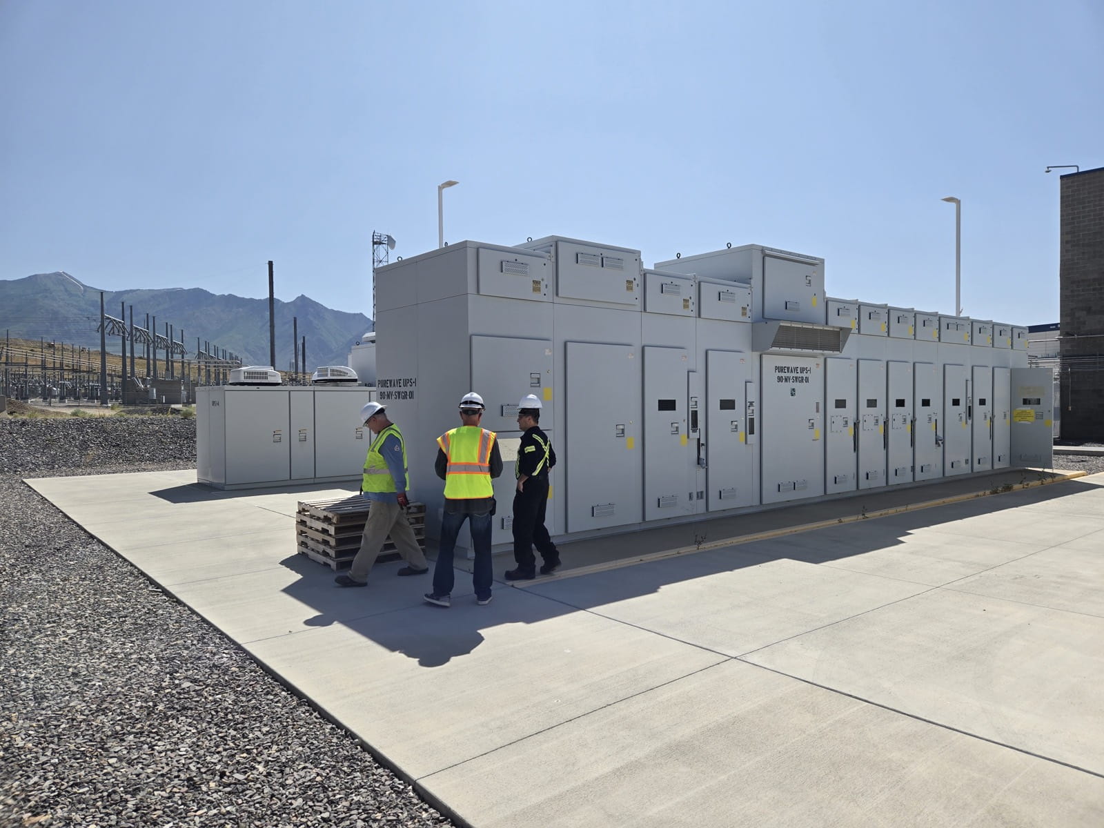
Medium-voltage UPS connected directly to the incoming bus for whole-plant protection. RE&D owns the design, supports the installed base with spares, field service and refurbishment, and can build to order.
- Transfers the load to the inverters typically within 1 to 4 ms (less than 1/4 cycle)
- Output matches the load for one minute at full load, or up to three minutes at reduced power
- Medium-voltage range: 2.5 to 20 MVA (2 to 16 MW) at 4 kV to 15 kV
- Low-voltage range: 250, 500, 750 and 1000 kW at 208-600 volts
- Electrically operated bypass breaker keeps the load on utility during maintenance
- Monitoring computer with local and remote Ethernet access, password protected
Overview
The PureWave UPS System protects critical loads from utility voltage disturbances and momentary interruptions. Under normal conditions the utility feeds the load through a power electronic switch; when a disturbance is detected the switch opens and battery-backed inverters supply the load through an isolation transformer.
The family is documented in two ranges: 2.5 to 20 MVA (2 to 16 MW) at 4 kV to 15 kV, and 250, 500, 750 and 1000 kW at 208-600 volts. Both are built from 250 kW battery modules and power conversion modules, with a bypass circuit breaker for maintenance and a monitoring computer for status and alarms.
- Rated power
- 250 kW – 16 MW
Specifications
Ratings: medium-voltage range (Instruction Sheet 653-510)
- Power rating
- 2.5 MVA - 20 MVA (2 MW - 16 MW)
- System voltage
- 4 kV - 15 kV
Ratings: 250-1000 kW range (Instruction Sheet 653-502)
- Power rating
- 250 kW, 500 kW, 750 kW and 1000 kW
- Voltage
- 208-600 V
Performance (both ranges)
- Transfer time
- Typically 1 to 4 milliseconds (less than 1/4 cycle)
- Output duration
- One minute at full load, or up to three minutes at reduced power
- Normal operation
- Utility supplies the load through the power electronic switch (PES); inverters start on a utility disturbance
- Operating states
- Ready, Run, Inhibit, Bypass, Bypass Isolate, Test in Bypass
Battery / Energy (both ranges)
- Battery module
- 250 kW battery module in each battery bay
- Automatic charge
- Two minutes of charge for each second of discharge at full load
- Equalize charge
- Automatic, every two months
Control & communications (both ranges)
- Monitoring
- Monitoring computer with local connection and remote access over Ethernet; username and password required
- Local display (250-1000 kW range)
- LCD screen display
- Alarm contacts
- System Warning and System Fault (standard); Low Battery, Load Overcurrent, UPS Running (optional)
- Generator interface
- Optional dry contact to the transfer switch
- Remote disable
- Optional normally closed input contact
Physical
- Enclosure bays (medium-voltage range)
- Battery bay, control bay, transformer bay
- Cooling
- Air conditioners with air-inlet and air-outlet vent hoods
Let's Solve Your Power Challenge.
Connect with our engineering team for a technical consultation. We'll help you identify risks and uncover efficiency opportunities.

Renewable Energy & Drives
5325 S Moorland RdNew Berlin, WI 53151United States

Severn Drives & Energy
Units 2 & 3, Kingsley Business ParkNew Road, Kibworth BeauchampLeicestershire, LE8 0LEUnited Kingdom
Start Your Consultation
Fill out the form below and we'll be in touch.