
PureWave® UPS XT System
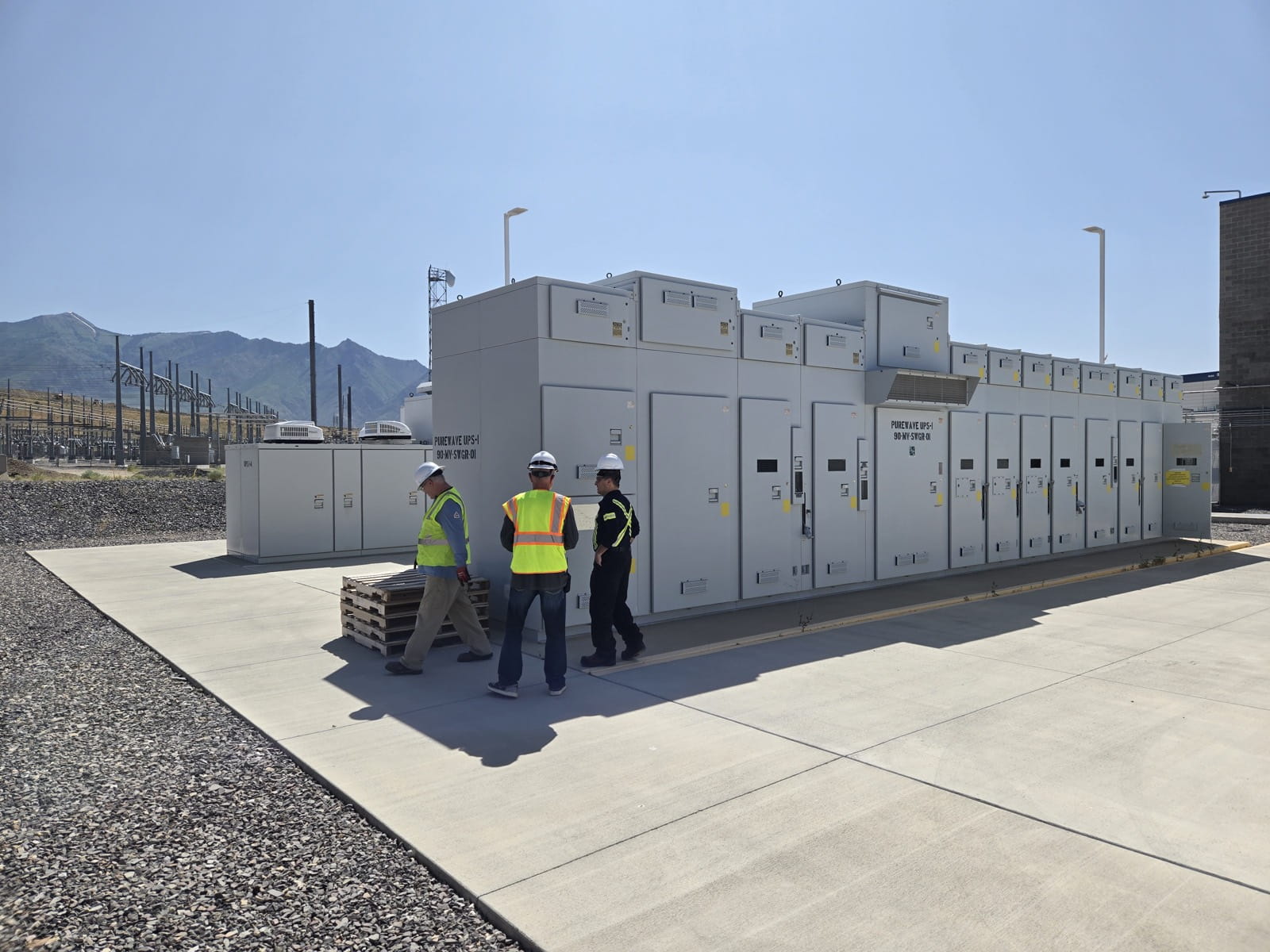
The extended-range medium-voltage platform, protecting up to 22.5 MW at voltages to 25 kV. Full lifecycle support, spares and field service available from RE&D.
- Rated 2.25 MW to 22.5 MW (2.5 MVA to 25 MVA) at 5 kV to 25 kV
- Transfers the load from utility to the UPS in typically 1/4 cycle on a disturbance
- Extended-runtime design in outdoor containers with batteries, IGBT inverters and dc-dc converters
- Power electronic switch uses series SCRs in an N+1 configuration
- Fire suppression (FP-40S) included and batteries integrated with dc load-break disconnect
- HMI control and monitoring on a master control rack, with SCADA control selectable
Overview
The PureWave UPS XT System is a three-phase, solid state, extended-runtime uninterruptible power supply that works alongside the existing building electrical system to provide backup power protection. It is a modular offline system suited to outdoor container installation.
Each container can hold two IGBT inverter modules, two dc-dc converter modules (choppers) and batteries, with the isolation transformer and medium-voltage switchgear external to the container. On a utility disturbance the power electronic switch opens and the system takes 100% of the load, typically within 1/4 cycle.
- Rated power
- 2.25 MW – 22.5 MW
Specifications
Ratings
- Power rating
- 2.25 MW - 22.5 MW (2.5 MVA - 25 MVA)
- System voltage
- 5 kV - 25 kV
- PCS ac output
- 480 Vac, wye three-wire, connected to the utility through a separate isolation transformer
- Inverter sections per PCS
- Two 1.125-MW inverter sections
- Inverter dc inputs
- Two 562.5-kW dc inputs per 1.125-MW inverter
- Maximum battery dc voltage
- 786 Vdc
Performance
- Topology
- Three-phase, solid state, extended-runtime UPS; modular offline system
- Transfer time
- Typically 1/4 cycle (power electronic switch, approximately 1/4 cycle)
- Power electronic switch
- Medium-voltage back-to-back SCR modules, series SCRs in an N+1 configuration
- Operating states
- Five: Ready, Run, Inhibit, Bypass, Bypass Isolate
Battery / Energy
- Energy storage
- Batteries housed in the container battery room, with dc-dc converters (choppers) to the inverters
- Battery disconnect
- Batteries in each rack integrated with a dc load-break disconnect
- Fire suppression
- FP-40S included
Physical
- Installation
- Outdoor container housing PCS and batteries
- Per container
- Two IGBT inverter modules, two dc-dc converter modules (choppers) and batteries
- External to container
- Isolation transformer (per container, dry-type, three-phase) and medium-voltage switchgear
- PCS enclosure
- Two dc bays, two inverter bays, one center ac section
Control & communications
- Control interface
- HMI computer on master control rack; password protected
- Control source
- Switchable between SCADA and HMI
- Manual controls
- Command Bypass Isolate key-lock, Command Bypass, Controlled By, Reset
- Switchgear
- Source, bypass, input, output, load and PCS circuit breakers; load bank test switch
Let's Solve Your Power Challenge.
Connect with our engineering team for a technical consultation. We'll help you identify risks and uncover efficiency opportunities.

Renewable Energy & Drives
5325 S Moorland RdNew Berlin, WI 53151United States

Severn Drives & Energy
Units 2 & 3, Kingsley Business ParkNew Road, Kibworth BeauchampLeicestershire, LE8 0LEUnited Kingdom
Start Your Consultation
Fill out the form below and we'll be in touch.